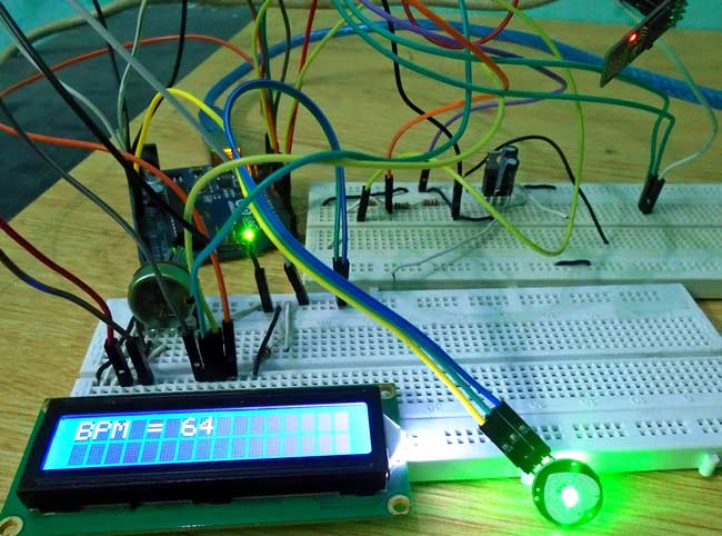
In this project we are going to make a Heart Beat Detection and Monitoring System using Arduino that will detect the heart beat using the Pulse Sensor and will show the readings in BPM (Beats Per Minute) on the LCD connected to it. It will also send the readings to ThingSpeak server using the Wi-Fi module ESP8266, so that Heart Beats can be monitored from anywhere in the world over the internet. ThingSpeak is a great source for displaying the data online and you can access the data from ThingSpeak at any time and at any place.
We have previously built a simple Heart Beat Monitor without showing data on Internet. This time we have used ThingSpeak to monitor the system over internet, and this will put this project into IOT category.
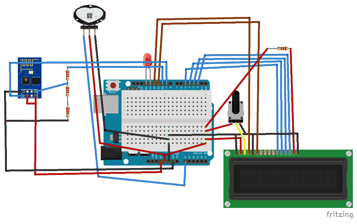
First of all we will connect the ESP8266 with the Arduino. ESP8266 runs on 3.3V and if you will give it 5V from the Arduino then it won’t work properly and it may get damage. Connect the VCC and the CH_PD to the 3.3V pin of Arduino. The RX pin of ESP8266 works on 3.3V and it will not communicate with the Arduino when we will connect it directly to the Arduino. So, we will have to make a voltage divider for it which will convert the 5V into 3.3V. This can be done by connecting three resistors in series like we did in the circuit. Connect the TX pin of the ESP8266 to the pin 9 of the Arduino and the RX pin of the ESP8266 to the pin 10 of Arduino through the resistors.
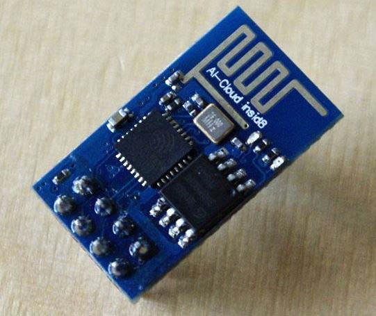
ESP8266 Wi-Fi module gives your projects access to Wi-Fi or internet. It is a very cheap device and make your projects very powerful. It can communicate with any microcontroller and it is the most leading devices in the IOT platform. Learn more about using ESP8266 with Arduino here.
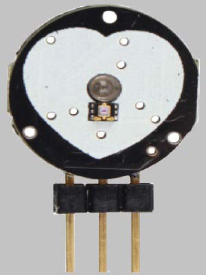
Then connect the Pulse Sensor with the Arduino. The connections of the pulse sensor are very easy. Pulse sensor has three pins. Connect 5V and the ground pin of the pulse sensor to the 5V and the ground of the Arduino and the signal pin to the A0 of Arduino.
Then connect the LED to pin 13 of Arduino. You do not have to connect a resistor with because the Arduino has built in resistor at pin 13.
In last, we will connect LCD with the Arduino. The connections of the LCD are as follows
Connect pin 11 (D4) to pin 5 of Arduino.
Connect pin 12 (D5) to pin 4 of Arduino.
Connect pin 13 (D6) to pin 3 of Arduino.
Connect pin 14 (D7) to pin 2 of Arduino.
ThingSpeak provides very good tool for IoT based projects. By using ThingSpeak site, we can monitor our data and control our system over the Internet, using the Channels and webpages provided by ThingSpeak. ThingSpeak ‘Collects’ the data from the sensors, ‘Analyze and Visualize’ the data and ‘Acts’ by triggering a reaction. We have previously used ThingSpeak in Weather station project using Raspberry Pi and using Arduino, check them to learn more about ThingSpeak. Here we are briefly explaining to use ThingSpeak for this IoT Heart Beat Monitoring Project.
First of all, user needs to Create a Account on ThingSpeak.com, then Sign In and click on Get Started.

After creating an account, go to channels and create a new channel. Now write the name of the Channel and name of the Fields. Also tick the check box for ‘Make Public’ option below in the form and finally Save the Channel. Now your new channel has been created.
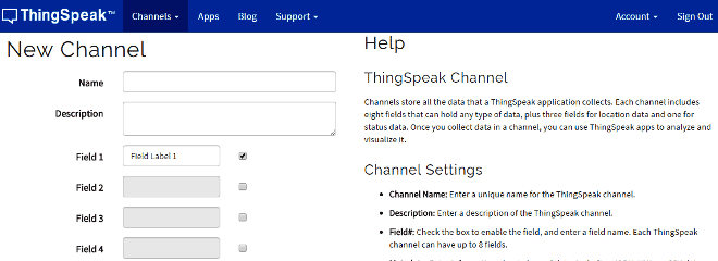
After this go to API keys and copy your Write API key. You will need this in the code. Check the Full Code at the end.
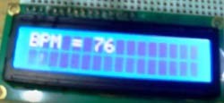
First we need to attach the Pulse Sensor to any organ of body where it can detect the pulse easily like finger, check the video below. Then the Pulse Sensor will measure the change in volume of blood, which occurs when every time heart pumps blood in the body. This change in volume of blood causes a change in the light intensity through that organ. The Arduino will then convert this change into the heart beat per minute (BPM). The LED connected at pin 13 will also blink according the Heart Beat.
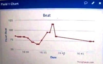
The ESP8266 will then communicate with the Arduino and will send the data to ThingSpeak. The ESP8266 will connect the network of your router that you will provide in the code and will send the data of the sensor online. This data on the ThingSpeak will be shown in a Graph form showing the past readings too and can be accessed from anywhere over internet. The LCD connected will also show you the BPM.
First of all, add the libraries. Software serial library is for enabling the RX and TX at pin 9 and pin 10. The default RX and TX pins of Arduino are pin 0 and 1 but if you want to enable it at other pins that you will have to use the software serial library. Then initialize the liquid crystal library (LiquidCrystal.h) and declare the pins at which you have connected the LCD.
#include #define DEBUG true SoftwareSerial esp8266(9,10); #include #include LiquidCrystal lcd(12,11,5,4,3,2);
Enter the Wi-Fi name, password and IP address of ESP8266. Then enter the API key from ThingSpeak that you saved earlier.
#define SSID "Your Wifi Name" #define PASS "Your Wifi Password" #define IP "184.106.153.149" String msg = "GET /update?key=9YS21NU0HY5YS1IKU";
The following code will start the LCD and will set the baud rate. Enter the baud rate according to your ESP8266. Every ESP8266 has its own baud rate. Some have baud rate of 9600, some have 115200 or other.
void setup() < lcd.begin(16, 2); lcd.print("circuitdigest.com"); delay(100); lcd.setCursor(0,1); lcd.print("Connecting. "); Serial.begin(9600); //or use default 115200. esp8266.begin(9600); Serial.println("AT"); esp8266.println("AT"); delay(5000); if(esp8266.find("OK"))< connectWiFi(); >interruptSetup(); >
Following function void updatebeat() will send the data at the IP address that we have entered and also will set the data in the field we set for heart beat.
void updatebeat() < String cmd = "AT+CIPSTART=\"TCP\",\""; cmd += IP; cmd += "\",80"; Serial.println(cmd); esp8266.println(cmd); delay(2000); if(esp8266.find("Error"))< return; >cmd = msg ; cmd += "&field1 rtejustify"> The following code will connect the ESP8266 with the Wi-Fi network that you entered earlier and then it will use this network to send the data to the ThingSpeak.
boolean connectWiFi()< Serial.println("AT+CWMODE=1"); esp8266.println("AT+CWMODE=1"); delay(2000); String cmd="AT+CWJAP=\""; cmd+=SSID; cmd+="\",\""; cmd+=PASS; cmd+="\""; . . . .
The following code will read the sensor and will convert the output of the sensor into heart beat per minute (BPM). It will also blink the LED connected at the pin 13 according to the BPM.
ISR(TIMER2_COMPA_vect) < cli(); Signal = analogRead(pulsePin); sampleCounter += 2; int N = sampleCounter - lastBeatTime; if(Signal < thresh && N >(IBI/5)*3)< if (Signal < T)< T = Signal; . . . ..
Further check the Full Code below, code has been well explained by comments can be easily understandable.
#include
#define DEBUG true
SoftwareSerial esp8266(9,10);
#include
#include
LiquidCrystal lcd(12,11,5,4,3,2);
#define SSID "Your Wifi Name" // "SSID-WiFiname"
#define PASS "Your Wifi Password" // "password"
#define IP "184.106.153.149"// thingspeak.com ip
String msg = "GET /update?key=9YS21NU0HY5YS1IKU"; //change it with your api key like "GET /update?key=Your Api Key"
//Variables
float temp;
int hum;
String tempC;
int error;
int pulsePin = 0; // Pulse Sensor purple wire connected to analog pin 0
int blinkPin = 13; // pin to blink led at each beat
int fadePin = 5;
int fadeRate = 0;
// Volatile Variables, used in the interrupt service routine!
volatile int BPM; // int that holds raw Analog in 0. updated every 2mS
volatile int Signal; // holds the incoming raw data
volatile int IBI = 600; // int that holds the time interval between beats! Must be seeded!
volatile boolean Pulse = false; // "True" when heartbeat is detected. "False" when not a "live beat".
volatile boolean QS = false; // becomes true when Arduino finds a beat.
// Regards Serial OutPut -- Set This Up to your needs
static boolean serialVisual = true; // Set to 'false' by Default. Re-set to 'true' to see Arduino Serial Monitor ASCII Visual Pulse
volatile int rate[10]; // array to hold last ten IBI values
volatile unsigned long sampleCounter = 0; // used to determine pulse timing
volatile unsigned long lastBeatTime = 0; // used to find IBI
volatile int P =512; // used to find peak in pulse wave, seeded
volatile int T = 512; // used to find trough in pulse wave, seeded
volatile int thresh = 525; // used to find instant moment of heart beat, seeded
volatile int amp = 100; // used to hold amplitude of pulse waveform, seeded
volatile boolean firstBeat = true; // used to seed rate array so we startup with reasonable BPM
volatile boolean secondBeat = false; // used to seed rate array so we startup with reasonable BPM
void setup()
lcd.begin(16, 2);
lcd.print("circuitdigest.com");
delay(100);
lcd.setCursor(0,1);
lcd.print("Connecting. ");
Serial.begin(9600); //or use default 115200.
esp8266.begin(9600);
Serial.println("AT");
esp8266.println("AT");
delay(5000);
if(esp8266.find("OK")) connectWiFi();
>
interruptSetup();
>
void loop() lcd.clear();
start: //label
error=0;
lcd.setCursor(0, 0);
lcd.print("BPM start"
>
void updatebeat() String cmd = "AT+CIPSTART=\"TCP\",\"";
cmd += IP;
cmd += "\",80";
Serial.println(cmd);
esp8266.println(cmd);
delay(2000);
if(esp8266.find("Error")) return;
>
cmd = msg ;
cmd += "&field1 \r\n";
Serial.print("AT+CIPSEND AT+CIPSEND >")) Serial.print(cmd);
esp8266.print(cmd);
>
else Serial.println("AT+CIPCLOSE");
esp8266.println("AT+CIPCLOSE");
//Resend.
error=1;
>
>
boolean connectWiFi() Serial.println("AT+CWMODE=1");
esp8266.println("AT+CWMODE=1");
delay(2000);
String cmd="AT+CWJAP=\"";
cmd+=SSID;
cmd+="\",\"";
cmd+=PASS;
cmd+="\"";
Serial.println(cmd);
esp8266.println(cmd);
delay(5000);
if(esp8266.find("OK")) Serial.println("OK");
return true;
>else return false;
>
>
void interruptSetup() <
TCCR2A = 0x02; // DISABLE PWM ON DIGITAL PINS 3 AND 11, AND GO INTO CTC MODE
TCCR2B = 0x06; // DON'T FORCE COMPARE, 256 PRESCALER
OCR2A = 0X7C; // SET THE TOP OF THE COUNT TO 124 FOR 500Hz SAMPLE RATE
TIMSK2 = 0x02; // ENABLE INTERRUPT ON MATCH BETWEEN TIMER2 AND OCR2A
sei(); // MAKE SURE GLOBAL INTERRUPTS ARE ENABLED
>
ISR(TIMER2_COMPA_vect) < // triggered when Timer2 counts to 124
cli(); // disable interrupts while we do this
Signal = analogRead(pulsePin); // read the Pulse Sensor
sampleCounter += 2; // keep track of the time in mS
int N = sampleCounter - lastBeatTime; // monitor the time since the last beat to avoid noise
// find the peak and trough of the pulse wave
if(Signal < thresh && N >(IBI/5)*3) < // avoid dichrotic noise by waiting 3/5 of last IBI
if (Signal < T)< // T is the trough
T = Signal; // keep track of lowest point in pulse wave
>
>
if(Signal > thresh && Signal > P) < // thresh condition helps avoid noise
P = Signal; // P is the peak
> // keep track of highest point in pulse wave
// NOW IT'S TIME TO LOOK FOR THE HEART BEAT
// signal surges up in value every time there is a pulse
if (N > 250) < // avoid high frequency noise
if ( (Signal > thresh) && (Pulse == false) && (N > (IBI/5)*3) ) <
Pulse = true; // set the Pulse flag when there is a pulse
digitalWrite(blinkPin,HIGH); // turn on pin 13 LED
IBI = sampleCounter - lastBeatTime; // time between beats in mS
lastBeatTime = sampleCounter; // keep track of time for next pulse
if(firstBeat) < // if it's the first time beat is found
firstBeat = false; // clear firstBeat flag
secondBeat = true; // set the second beat flag
sei(); // enable interrupts again
return; // IBI value is unreliable so discard it
>
word runningTotal = 0; // clear the runningTotal variable
for(int i=0; i rate[i] = rate[i+1]; // and drop the oldest IBI value
runningTotal += rate[i]; // add up the 9 oldest IBI values
>
rate[9] = IBI; // add the latest IBI to the rate array
runningTotal += rate[9]; // add the latest IBI to runningTotal
runningTotal /= 10; // average the last 10 IBI values
BPM = 60000/runningTotal; // how many beats can fit into a minute? that's BPM!
QS = true; // set Quantified Self flag
// QS FLAG IS NOT CLEARED INSIDE THIS ISR
>
>
if (Signal < thresh && Pulse == true)< // when the values are going down, the beat is over
digitalWrite(blinkPin,LOW); // turn off pin 13 LED
Pulse = false; // reset the Pulse flag so we can do it again
amp = P - T; // get amplitude of the pulse wave
thresh = amp/2 + T; // set thresh at 50% of the amplitude
P = thresh; // reset these for next time
T = thresh;
>
if (N > 2500) < // if 2.5 seconds go by without a beat
thresh = 512; // set thresh default
P = 512; // set P default
T = 512; // set T default
lastBeatTime = sampleCounter; // bring the lastBeatTime up to date
firstBeat = true; // set these to avoid noise
secondBeat = false; // when we get the heartbeat back
>
sei();
// enable interrupts when youre done!
>// end isr
